
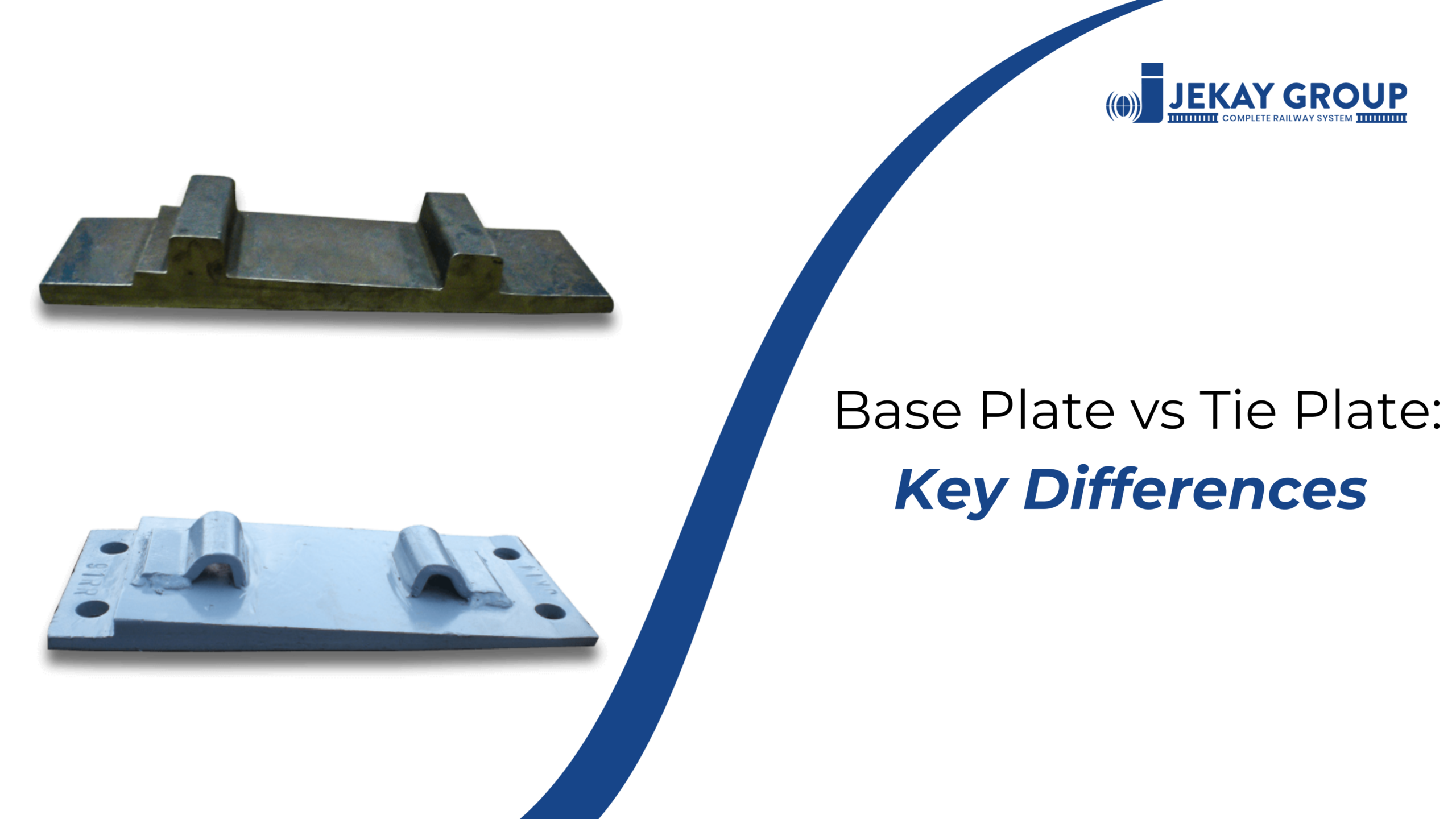
The terms “base plate” and “tie plate” are frequently used within the railway industry to describe the same component. However, in structural construction, they refer to distinct elements with different mechanical functions. This terminological overlap can lead to specification errors and procurement issues. Data indicates that approximately 34% of railway procurement errors involve the misidentification of structural components.
This document establishes the technical distinctions between these components, their application contexts, and the engineering standards required for accurate specification in structural and railway engineering projects.
Understanding Base Plates and Tie Plates
What Is a Structural Base Plate?
A structural base plate is a flat steel plate positioned between a steel column and concrete foundation. Its primary function transfers the column’s vertical load across a larger concrete area, preventing crushing. A typical 300mm × 300mm × 20mm base plate spreads a 1,500 kN column load to 16.7 MPa bearing pressure—well within concrete’s 20-30 MPa capacity.
Anchor bolts embed through the plate into concrete, resisting tension and shear forces. Grout fills the gap between plate and foundation for uniform load distribution.
What Is a Railway Tie Plate?
A railway tie plate (also called base plate or sole plate in rail contexts) sits between the rail foot and sleeper. It distributes wheel loads from the narrow rail base (125-150mm wide) across a 150-200 cm² bearing area, reducing contact pressure on wooden or concrete sleepers.
Without tie plates, concentrated 125 kN vertical forces from a 25-ton axle would exceed wooden sleeper compressive strength (8-12 MPa), crushing fibers at rail seats.
The Terminology Overlap Explained
In railway engineering, “tie plate,” “base plate,” and “sole plate” refer to the same component. Industry sources confirm this interchangeability: “The railway tie plate, which also can be called as railway base plate or sole plate”.
In structural engineering, “base plate” means something entirely different—the column-to-foundation connection plate. Context determines which component you’re discussing.
Primary Functions: What Each Component Does
Structural Base Plate Functions
- Load distribution: Spreads concentrated column loads (axial, bending) to wider concrete area
- Leveling: Allows adjustment using shims if concrete surface isn’t perfectly flat
- Connection: Links steel superstructure to concrete substructure via anchor bolts
- Stability: Provides temporary support during column erection before permanent connections
Railway Tie Plate Functions
- Load spreading: Increases bearing area by 2-3× compared to direct rail-sleeper contact
- Gauge maintenance: Raised shoulders resist lateral rail movement during cornering
- Sleeper protection: Prevents crushing of wood fibers or cracking of concrete under repeated loads
- Vibration reduction: Reduces noise transmission, critical for urban transit applications
- Rail cant provision: 1:40 inclination tilts rail inward for correct wheel-rail contact geometry
Proper tie plates extend sleeper life by 40-60% compared to direct rail contact.
Location and Application Context
Where Structural Base Plates Apply
Structural base plates connect steel columns to concrete foundations in:
- Commercial and industrial buildings
- Bridge substructures
- Steel-frame towers and transmission structures
- Heavy machinery foundations
Where Railway Tie Plates Apply
Railway tie plates install between rails and sleepers in:
- Mainline railway tracks (wooden, concrete, or steel sleepers)
- Crane rail systems in industrial facilities
- Transit and metro track systems
- Ballastless slab track applications
Material Composition Comparisons
Structural Base Plate Materials
- Mild steel (common for standard loads)
- High-strength steel grades for heavy columns
- Material selection based on load requirements and building codes
Railway Tie Plate Materials
- Mild steel (Q235 carbon steel for standard applications)
- Cast iron (durable but brittle under impact)
- Cast steel (higher strength for heavy-duty use)
- Forged steel (highest strength for extreme conditions)
- Alloy steel (superior fatigue resistance for high-speed lines)
Higher-strength alloy steels with tensile strength exceeding 600 MPa serve heavy-haul corridors where fatigue resistance matters more than upfront cost.
Design Features That Define Performance
Structural Base Plate Design
- Flat plate shape (square or rectangular)
- Size determined by load and concrete bearing capacity (A₁ = Load/Allowable Bearing Stress)
- Thickness calculated to resist bending as cantilever (typically 20-50mm)
- Anchor bolt holes positioned for embedment depth
- Optional stiffeners for heavy moment transfer
Railway Tie Plate Design
- Tapered ends: Improve stability and reduce edge stress concentrations
- Shoulder configurations: Single shoulder, double shoulder, or hook twin (AREMA)
- Hole patterns: Ø26mm (4×) or Ø36.3mm (2×) for spikes/bolts
- Cant incline: Typically 1:40 for proper rail tilt
- Raised shoulders: 15-25mm high to grip rail base and prevent lateral creep
- Ribbed undersides: Increase bending resistance by 40-60% without proportional weight increase
Types and Variations by Application
Structural Base Plate Types
- Slab base (pinned): Simple plate with cleat angles for pinned conditions
- Stiffened base (fixed): Includes angles and stiffeners for rigid moment transfer
- Embedded plates: Partially embedded in concrete for better anchoring
- Standoff base: Used for light poles/signs with gap for inspection
Railway Tie Plate Types
- Single shoulder tie plate: Unilateral lateral restraint for standard track
- Double shoulder tie plate: Bilateral restraint for heavy freight and high-speed applications
- Hook twin tie plate: AREMA standard with enhanced grip
- Cast-in base plates: Embedded during concrete sleeper manufacturing
- Surface-mounted plates: Attached via pre-cast anchor bolts for replacement flexibility
- Direct fixation tie plates: Integrate with elastic fastening systems
Double-shoulder plates provide bilateral restraint suited to heavy freight where lateral forces are significant.
Fastening and Installation Methods
Structural Base Plate Installation
- Anchor bolts embedded in concrete before plate placement
- Grout fills gap between plate and concrete after leveling
- Leveling nuts and shims adjust for surface irregularities
- Temporary supports hold columns vertical during erection
Railway Tie Plate Installation
- Wooden sleepers: Cut spikes, screw spikes, or coach screws driven through plate holes
- Concrete sleepers: Cast-in anchoring or surface-mounted bolts (150-250 Nm torque)
- Steel sleepers: Bolts through pre-drilled holes (200-300 Nm torque)
- Rubber or elastomeric pads between plate and concrete reduce vibration and prevent crushing
Rubber-padded plates reduce sleeper cracking by up to 35% on heavy-haul lines.
Standards Governing Specifications
Structural Base Plate Standards
- AISC Design Guide 01 (Base Plate and Anchor Rod Design)
- Local building codes (IS codes in India, ACI in US, Eurocode in Europe)
Railway Tie Plate Standards
- AREMA (American Railway Engineering and Maintenance-of-Way Association)
- GB standards (Chinese railway specifications)
- JIS E1110 (Japanese Industrial Standards)
- UIC 864-6 (International Railway Union)
- UIC 54, UIC 60 rail section specifications
- RDSO (Indian Railway Research, Design and Standard Organisation)
Key Differences Summary Table
| Aspect | Structural Base Plate | Railway Tie Plate |
| Industry | Building/construction steelwork | Railway track engineering |
| Position | Column bottom to concrete foundation | Rail foot to sleeper top |
| Primary Load | Axial column load (500-3,000 kN) | Wheel load (100-160 kN per axle) |
| Bearing Area | 90,000-250,000 mm² | 15,000-20,000 mm² |
| Thickness | 20-50mm | 6-12mm (wooden), 8-12mm (concrete) |
| Fastening | Anchor bolts embedded in concrete | Spikes or bolts into sleepers |
| Special Features | Stiffeners, grout pockets | Shoulders, cant incline, ribs |
| Service Life | 30-50+ years | 15-40 years depending on sleeper type |
Choosing the Right Component for Your Project
When You Need a Structural Base Plate
Specify structural base plates for:
- Steel column foundations in buildings or bridges
- Equipment foundations requiring column-to-concrete connection
- Structures where anchor bolt resistance to tension/shear is required
When You Need a Railway Tie Plate
Specify railway tie plates for:
- New track construction or track rehabilitation
- Crane rail systems in factories and warehouses
- Transit/metro track projects
- Applications requiring gauge stability and sleeper protection
Specification Criteria Checklist
For railway tie plates, specify:
- Rail section (52 kg, 60 kg, 90 UTS, UIC 54, UIC 60)
- Sleeper type (wooden, concrete, steel)
- Required cant (1:20, 1:40, or flat)
- Fastening system compatibility (spike holes, clip shoulders)
- Service conditions (axle loads, curve radius, corrosive environment)
Request material certifications showing rolling, casting, or forging route with mechanical properties verified.
FAQs
Q: Is a tie plate the same as a base plate?
A: In railway contexts, yes—they’re interchangeable terms for the plate between rail and sleeper. In structural engineering, “base plate” means the column-to-foundation plate, which is completely different. Context determines which component is being discussed.
Q: What material is best for railway tie plates?
A: Q235 carbon steel dominates standard applications for cost-effectiveness. Heavy-haul corridors and high-speed lines require higher-strength alloy steels (tensile strength >600 MPa) for superior fatigue resistance.
Q: What are the different shoulder types for tie plates?
A: Single shoulder provides unilateral lateral restraint for standard track. Double shoulder offers bilateral restraint for heavy freight and high-speed applications. Hook twin tie plates follow AREMA standards with enhanced rail grip.
Q: How does base plate thickness affect load distribution?
A: Thicker plates (8-12mm for railway, 20-50mm for structural) resist bending better, maintaining uniform pressure distribution. Thin plates flex excessively, creating higher edge pressure. However, optimal thickness balances stiffness with ability to accommodate sleeper surface irregularities.
Q: Why specify ribbed base plates instead of flat ones?
A: Ribs increase bending resistance by 40-60% without proportional weight increase. They prevent plate embedment into concrete sleepers under repeated loading. The 15-25% cost premium justifies itself through extended service life and reduced sleeper damage.
Conclusion
Base plates and tie plates serve entirely different industries—structural construction versus railway track engineering. The terminology overlap in rail contexts (where “tie plate,” “base plate,” and “sole plate” mean the same component) creates confusion only when you miss the context. Specify by application: column-to-foundation connection means structural base plate; rail-to-sleeper interface means railway tie plate. Match plate characteristics to sleeper type, service loads, and fastening systems to prevent premature failures.
About Jekay International Track
Jekay International Track Pvt. Ltd. manufactures rail base plates engineered for load distribution across wooden, concrete, and steel sleeper applications. Since 1980, we’ve delivered precision base plates serving railway projects in 13+ countries, meeting RDSO, IRS, and international railway standards (AREMA, UIC, JIS). Our engineering team analyzes your sleeper type, track loading, and environmental conditions to recommend base plates optimized for your specific infrastructure.
